|


|
|

|
Technology
MFC
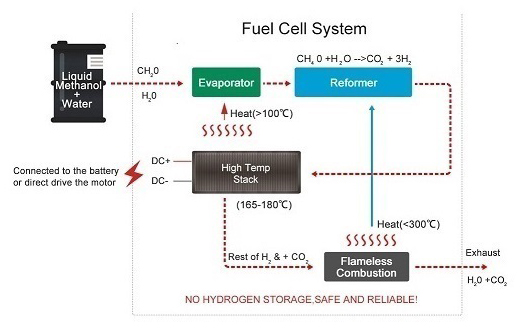
Methanol reformed fuel cell integrated methanol reforming technology, hydrogen fuel cell technology, develop individual products, meet the demand of different application scenarios.
300W Methanol Fuel Cell
300 W power output. Air-cooled operation. Built-in lithium battery, no external power supply required. A mobile battery charger capable of supplying controlled off-grid power, typically for charging 24 V lithium battery packs. Configurable LV/HV power output. Simple installation and autonomous operation.
1KW-3KW Methanol Fuel Cell
1KW-3KW power output. Simpler structure, smaller size, lighter in weight. Higher fuel efficiency. Competitive cost. Simpler control system and higher reliability. Excellent environmental adaptability. Quick startup, good dynamic performance.
5KW Methanol Fuel Cell
5 kW power output. Simpler structure, smaller size, lighter in weight. Higher fuel efficiency. Competitive cost. Simpler control system and higher reliability. Excellent environmental adaptability. Quick startup, good dynamic performance.
20KW Methanol Fuel Cell
20 kW power output. Compact design, highly integrated system. Designed for mobile applications. High fuel efficiency. Quick start up, good dynamic performance. Configurable LV/HV power output. Good stability and environmental adaptability.
PEMFC
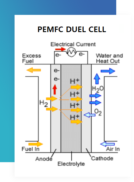
Proton-Exchange Membrane Fuel Cell
A Promising Technology for Sustainable Energy
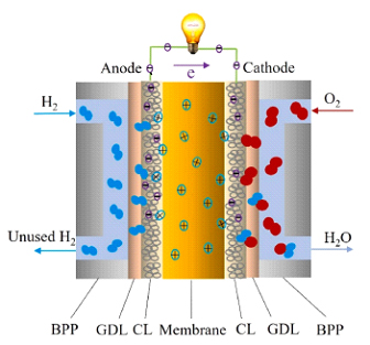
Proton-exchange membrane fuel cells are a type of fuel cell that has gained significant attention in recent years due to their potential for a wide range of applications. They typically convert hydrogen into electrical energy through an electrochemical process.
PEMFC Components
-
Anode
The anode is where the fuel (hydrogen) is oxidized, releasing electrons and protons.
-
Proton Exchange Membrane (PEM)
The PEM acts as a barrier that allows protons to pass through while blocking electrons.
-
Cathode
The cathode is where oxygen reduction occurs, combining electrons from the anode with oxygen molecules to form water.
Advantages of PEMFCs
-
Low Operating Temperature
The anode is where the fuel (hydrogen) is oxidized, releasing electrons and protons.
-
High Power Density
PEMFCs can achieve high power densities, enabling them to power compact and lightweight devices.
-
Quick Start-up and Shutdown
PEMFCs can start up and shut down quickly, making them well-suited for transportation applications.
-
Low Emissions
PEMFCs produce only water and heat as byproducts, contributing to minimal environmental impact.
Applications of PEMFCs
-
Transportation
PEMFCs are being developed for use in electric vehicles, buses, and even ships.
-
Stationary Power
PEMFCs can be used as stationary power sources for backup power, remote communities, and off-grid applications.
DMFC
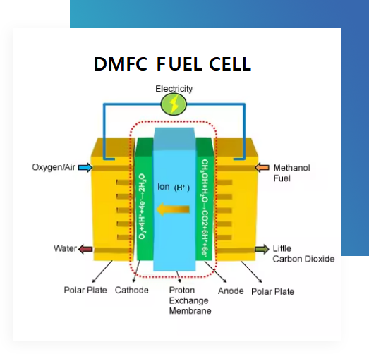
A Direct Methanol Fuel Cell (DMFC) is an electrochemical energy conversion device which transforms the chemical energy of liquid methanol into electrical energy directly without any intermediate processes or moving parts, thus making it an efficient source of power. Unlike internal combustion engines that burn fuel for power, direct methanol fuel cells (DMFCs) use a polymer electrode membrane to convert chemical energy to electrical energy.
Methanol fuel is delivered to the anode side of the membrane, where it is split into protons and electrons. The electrons pass to a circuit and create electrical current, while the protons pass through the membrane to the cathode side of the fuel cell. On the cathode side, the protons and oxygen form carbon dioxide and water.
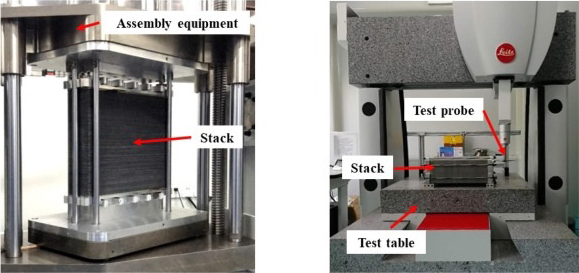
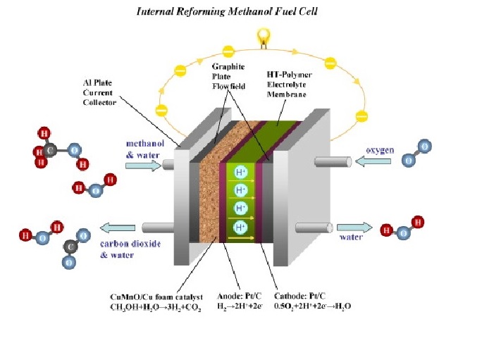
Stack Design
A mixture of methanol and water is reformed to H₂ and CO₂ in the equipment. Then, H₂ and CO₂ are guided into the fuel cell stack. In the stack, the hydrogen gas is reacted with the catalyst in the anode, which is separated into electrons and protons. The proton passes through the PEM to combine with oxygen and electrons in the cathode to form water vapor. The electrons go through the external circuit and form a direct current.
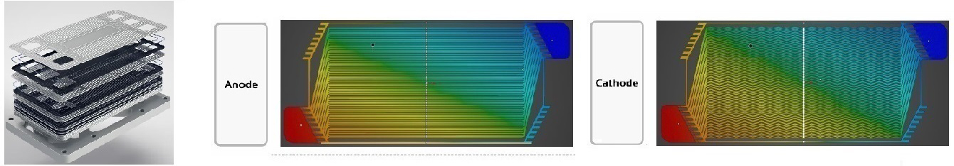
Bipolar Pattern Design
A mixture of methanol and water is reformed to H₂ and CO₂ in the equipment. Then, H₂ and CO₂ are guided into the fuel cell stack. In the stack, the hydrogen gas is reacted with the catalyst in the anode, which is separated into electrons and protons. The proton passes through the PEM to combine with oxygen and electrons in the cathode to form water vapor. The electrons go through the external circuit and form a direct current.
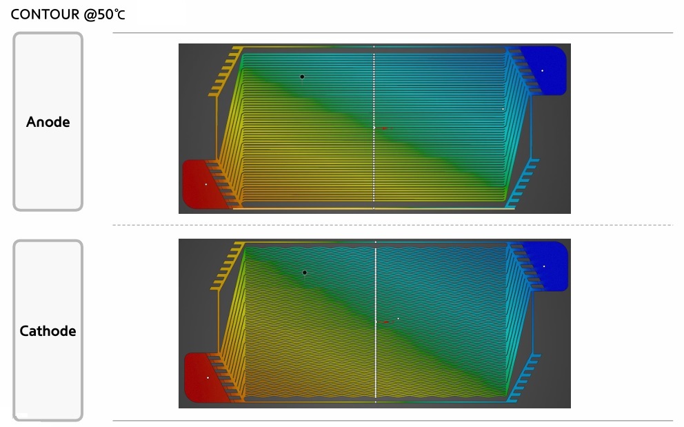
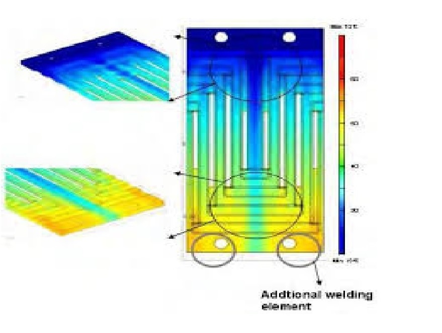
FEM Analysis
A simple introduction to the Finite Element Method (FEM), how a Finite Element Analysis (FEA) workflow looks like and how it is used in the industry.
What is the Finite Element Method?
For the vast majority of geometries and problems, Partial Differential Equations cannot be solved with analytical approaches. Instead, we can approximate these equations using discretisation methods that can be solved using numerical methods.
Therefore, the solutions we get are also an approximation of the real solution to those PDEs. The FEM is such an approximation method that subdivides a complex space or domain into a number of small, countable, and finite amount of pieces (thus the name finite elements) whose behaviour can be described with comparatively simple equations.
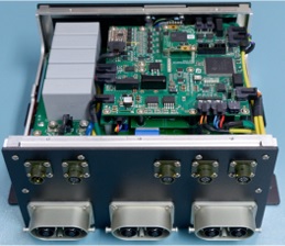
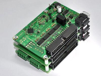
Control
Switching Multi-Function Control technology
Remote Awake and Debugging technology
A fuel cell control unit (FCCU) is the brain of a fuel cell system, managing electricity generation and ensuring safe operation. It monitors and controls the fuel cell stack, integrates various subsystems, and utilizes advanced strategies to optimize performance and efficiency. Different FCCU types exist for air-cooled or liquid-cooled systems, with some offering a compact integrated design. As fuel cell technology advances, FCCUs will remain vital for clean and efficient energy solutions.
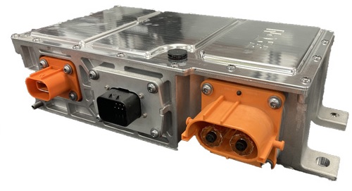
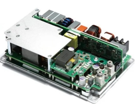
DCDC Converter
DC-DC converters are workhorses of electronics, efficiently boosting or reducing voltage levels to power various devices. They use inductors, transistors, and capacitors to regulate power and come in types like buck (step-down) and boost (step-up) converters. Widely used in electronics from laptops to cars. thev offer high efficiency. compact size. and precise voltage control. As electronics evolve. DC-DC
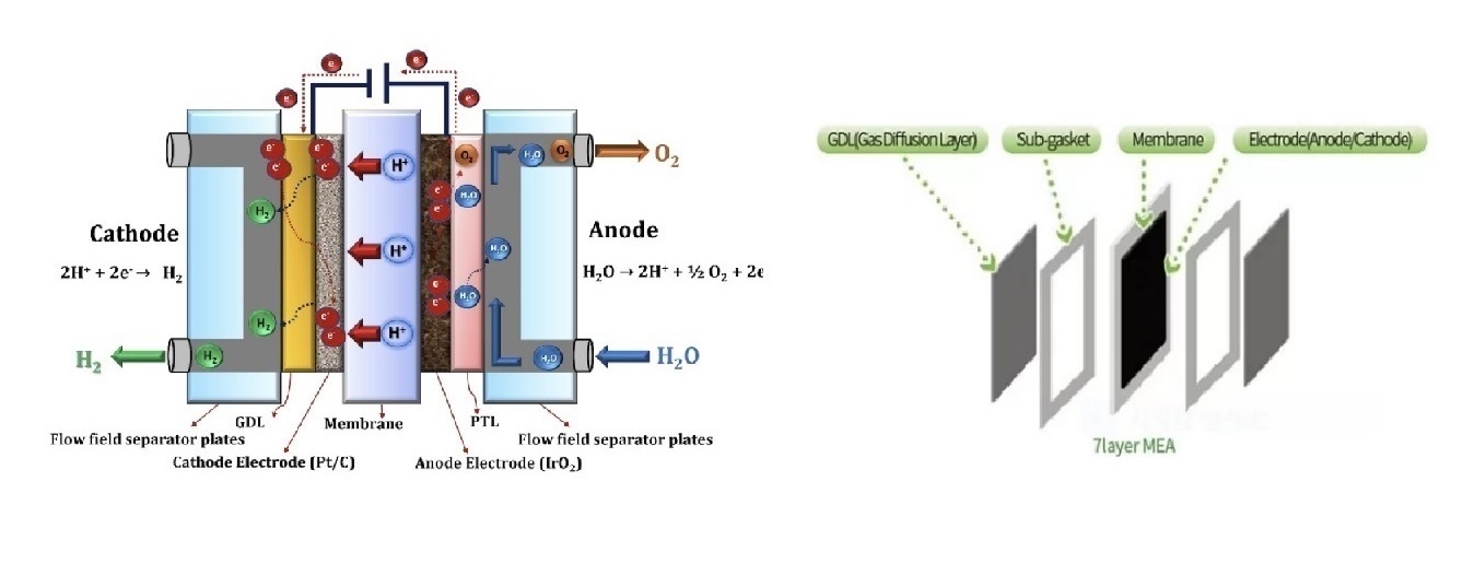
MEA
Membrane Electrode Assembly (MEA) for Fuel Cells A membrane electrode assembly (MEA) is a key component of proton exchange membrane fuel cells (PEMFCs) and other types of fuel cells. It consists of a thin proton-conducting electrolyte membrane sandwiched between two catalyst layers. The catalyst layers are typically made of platinum or platinum alloys and are responsible for catalyzing the electrochemical reactions that generate electricity.
Here are the main components of an MEA:
Proton-conducting electrolyte membrane: The membrane allows protons (H+) to pass through while blocking electrons. Common materials include perfluorosulfonic acid (Nafion) and sulfonated polyimides.
Catalyst layers: The catalyst layers are located on either side of the membrane and are responsible for catalyzing the electrochemical reactions. Platinum is the most common catalyst, but other metals and alloys are also being investigated.
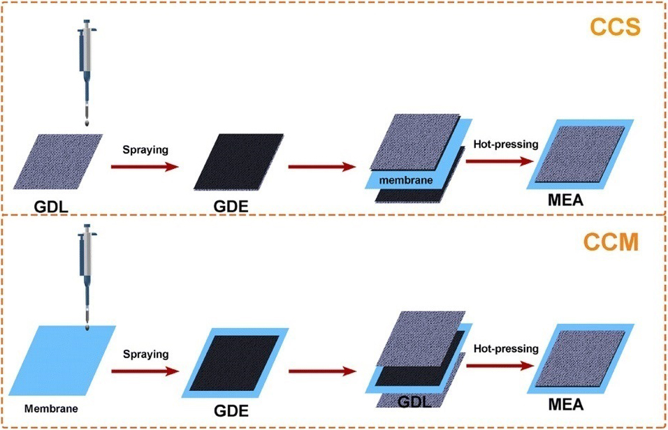
CCM coating technology
CCM (Catalyst Coated Membrane) is a type of membrane electrode assembly (MEA) used in proton exchange membrane fuel cells (PEMFCs). It consists of a thin proton-conducting electrolyte membrane sandwiched between two catalyst layers. The catalyst layers are typically made of platinum or platinum alloys and are responsible for catalyzing the electrochemical reactions that generate electricity.
Here are some of the advantages of CCM MEAs: Low resistance: The catalyst layer is in direct contact with the electrolyte membrane, which reduces the electrical resistance between the anode and cathode.
High power density: CCM MEAs can achieve high power densities because the catalyst layer is thin and uniform.
Good durability: CCM MEAs are relatively durable and can withstand a wide range of operating conditions.
CCS coating technology
The CCS process with MEA typically involves the following steps:
Flue gas from a power plant or other industrial source is passed through a scrubber containing an MEA solution. The MEA absorbs the CO2 from the flue gas, leaving behind a cleaner stream of gas that can be released into the atmosphere.
The CO2-rich MEA solution is then transported to a storage site, typically a deep underground geological formation.
Storage: The CO2-rich MEA solution is injected into the storage formation, where the CO2 is trapped and prevented from re-entering the atmosphere.
MEA-based CCS has several advantages:
High CO2 capture efficiency: MEA can capture up to 90% of the CO2 from flue gas.
Relatively mature technology: MEA-based CCS has been demonstrated at pilot and commercial scale.
Widely available: MEA is a readily available and relatively inexpensive chemical.
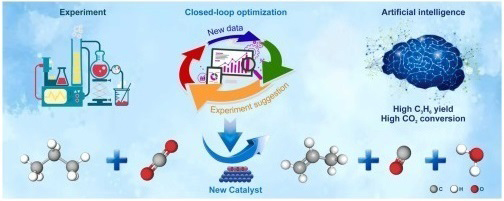
Optimized Catalyst & Slurry Recipe
The development of optimized catalyst and slurry recipes is crucial for enhancing the performance and efficiency of fuel cells. Catalysts play a pivotal role in accelerating the electrochemical reactions that generate electricity within fuel cells, while slurries ensure the uniform dispersion of catalysts onto the electrode surface. Optimizing these components requires careful consideration of various factors, including catalyst composition, particle size, slurry viscosity, and electrode preparation techniques.
Catalyst Optimization:
Catalyst Composition: The selection of appropriate catalyst materials is essential for achieving high catalytic activity and selectivity. Common catalysts for fuel cells include platinum, platinum alloys, and non-precious metal catalysts. The choice of catalyst depends on the fuel cell type, operating conditions, and desired performance metrics.
Particle Size: Catalyst particle size significantly impacts the surface area and active sites available for electrochemical reactions. Smaller catalyst particles generally offer a higher surface area, leading to enhanced catalytic activity. However, excessively small particles may result in agglomeration, reducing the active surface area.
Reformer
Renewable methanol (Green methanol) 기술
Renewable methanol (Green methanol) 기술
A mixture of methanol and water is reformed to H₂ and CO₂ in the equipment. Then, H₂ and CO₂ are guided into the fuel cell stack. In the stack, the hydrogen gas is reacted with the catalyst in the anode, which is separated into electrons and protons. The proton passes through the PEM to combine with oxygen and electrons in the cathode to form water vapor. The electrons go through the external circuit and form a direct current.
|
301, Ace Tower G9, 649 Jagok-dong, Gangnam-gu, Seoul.Korea FAX : 82 504 327 8581 E-MAIL : sales@cellatti.net Hosting by CGIMALL Business Registration : 521-86-03212 Copyright(c) CellATTi Inc All Rights Reserved
|